READ MORE: Crystal LED For Virtual Production White Paper Now Available (SonyCine)
Virtual production and in-camera visual effects (ICVFX) demand a new and unique set of performance requirements in both LED displays and cinema cameras. Most of these technical attributes are well understood — including pixel uniformity, luminance, black level performance, off-axis color shift, and scanning artifacts.
What has not been explored is the specific impact of these specifications for virtual production. Sony and Epic Games conducted a series of tests to learn more about the impact of LED wall technology on workflow and final picture performance.
Its broad conclusion is to marry a high-end cine camera (like a Sony Venice) with a fine-pitch LED display (such as the company’s own Crystal product), but also reveals a number of important general principles that apply to LED choice and on-set performance:
Wait, What Is ICVFX?
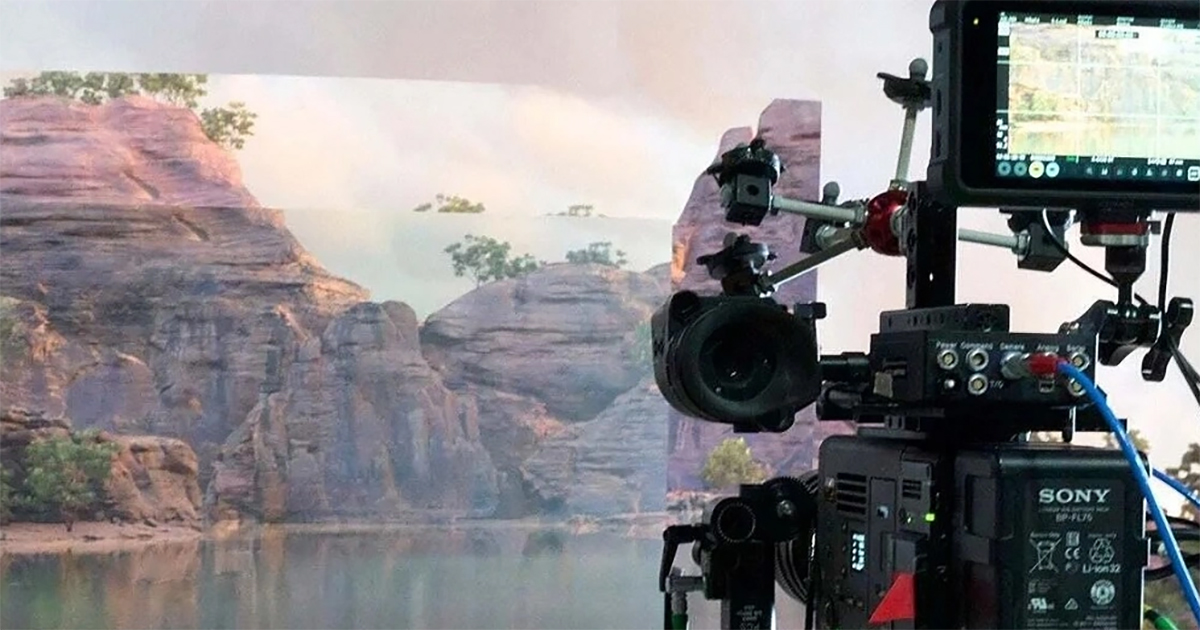
ICFVX is the process of capturing visual effects live and in-camera on set, such as within an LED volume. This can be thought of as simply a workflow in which traditional green screen stages are replaced with LED displays to capture visual effects in-camera and in real-time. During ICVFX, game-engine technology is used to render background images on LED walls while the camera captures the total composited scene.
Scenes that previously may have taken hundreds of hours to compose, shoot, render and composite, might now be accomplished in real-time, in-camera and on-set. Remarkably, in-camera visual effects can work when capturing both 3D worlds, as in the case of Disney’s The Mandalorian, or with 2D plates, such as in a driving sequence.
In addition to the ability to shoot multiple complex scenes efficiently on a single set, ICVFX offers efficiency in other areas, such as capturing environmental lighting and reflections in real-time — thereby reducing the need for post-production compositing, which is needed with green-screen productions.
LED Walls: The Basics
“Most commercially available LED displays use almost the same, or a very similar set of third-party components and design configurations,” the white paper notes. These include utilizing mini-LED size chips arranged in surface mount device (SMD) enclosures, positioning of 2.5 to four millimeter pixel pitch, off-the-shelf driver circuits, and image processing chips and printed circuit boards (PCB) with technology to reduce surface reflectivity.
LED displays intended for other applications, such as concert touring, conference rooms and signage, will often not be designed with the precision needed for an on-set virtual production environment.
For displays found in VP volumes, the spacing between pixels — referred to as the pixel pitch — is typically between one to four millimeters. Since fine pixel pitch displays are more costly on a per-area basis (cost per square meter or square foot), larger pixel pitch units are often used for less-demanding floor or ceiling portions of the volume or for background plates in very large stages. On the other hand, smaller stages, such as those roughly 26 feet (eight meters) or less in width, require finer pixel pitch, typically in the 1.25 to 2.5 millimeter range, to avoid individual pixels being visible on camera at typical shooting distances.
Different Types of LED
Direct-view LED (light-emitting diode) displays are constructed from a dense matrix of pixels, each incorporating an individual red, green and blue (RGB) LED emitter.
The LED pixels are fabricated on a substrate within cabinets to create the LED display. The cabinets are mounted side-by-side and top to bottom in sturdy structural frames and carefully aligned to avoid visible seams or gaps. The frame can be flat on a virtual production stage, but is often engineered to form a concave curve surrounding the set area. The video image is fed through a game engine, such as Epic Games’ Unreal Engine, and segmented and distributed to the many LED cabinets from one or more LED image processors. Standard LEDs consist of a semiconductor light source, measuring roughly one millimeter across and emitting light of a defined wavelength (color) when a current flows.
For fine pixel pitch LED displays, mini-LED technology is used with LED chips as small as 200 microns across. For even higher-density fine pitch displays, LED chips are now available, with chip sizes as small as 20 to 100 microns in size. These enable high-definition images even on modest-size panels.
These “standard” (or inorganic) LEDs differ in performance and behavior from organic LEDs (OLED) and liquid crystal displays (LCD). Mini-LED and LED technology is uniquely suited for virtual production due to its excellent contrast ratios, color reproduction, wide viewing angle, high brightness, consistent performance, and long life.

Picture Performance
The final “look” of the virtual production is impacted by the interaction between the selected LED display performance and the selected cinema camera — especially lens and sensor characteristics — along with the real-time rendering engine, motion tracking systems, and stage lighting.
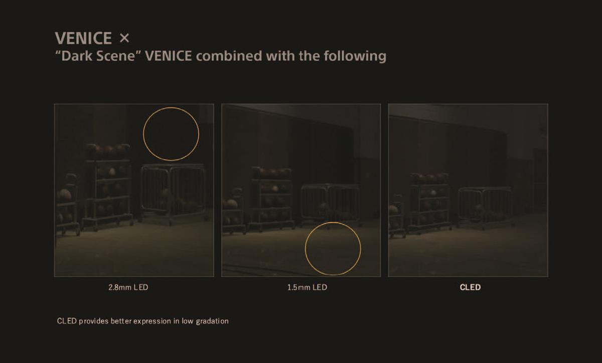
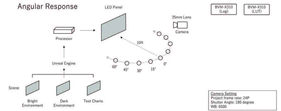
Of particular interest are the displays’ reflectivity of ambient light off the display surface, their ability for low-level greyscale representation and color accuracy — especially those that offer consistency when viewed from both on-axis and an oblique angle — and other features.
A typical studio environment will, by its nature, include a significant level of ambient light from studio luminaires and on-set practical lights. In order to avoid specular reflections, flare, or washed-out contrast, it is important that the LED display surface reflect ambient light diffusely, minimizing the specular component that arrives back into the camera as much as possible.
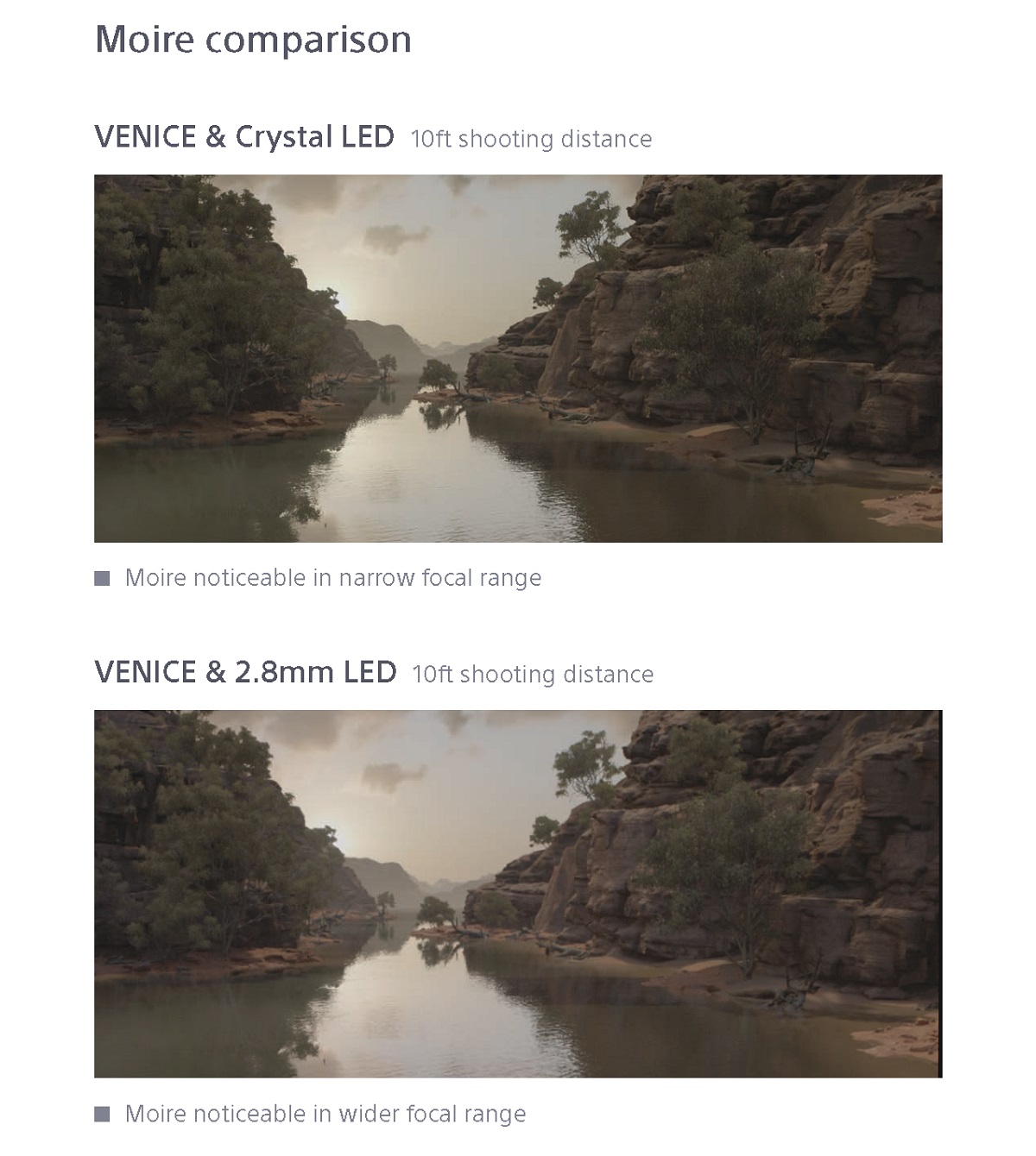
Moiré is an undesirable interference pattern caused by the interaction between similar patterns that are overlaid on each other. In the case of virtual production, Sony combines a cinema camera featuring a sensor arranged in a Bayer pattern with an LED display that features diodes arranged in a similar grid. The relationship between the pixel pitch, density of camera sensor photosites, shooting distance, lens focal length, and depth of field all influence whether Moiré patterns become visible in the shot.
De-focusing the camera by using a narrower depth of field may also help reduce Moiré visibility, but at the expense of limiting creative choices. Other factors, such as the design of the optical low pass filter (OLPF) in the camera will also influence the Moiré visibility and so should be a consideration when selecting the best solution for a particular production.
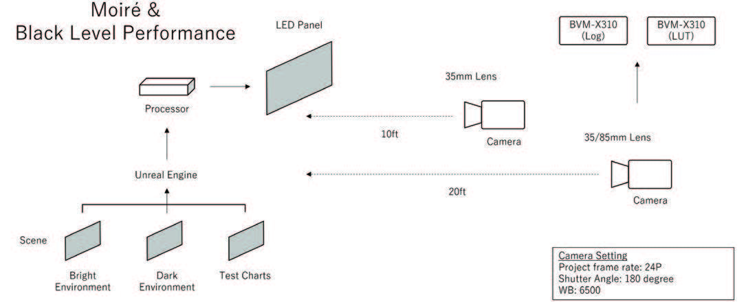
In testing, Sony found that many variables impacted the presence of scanline artifacts, which was further compounded by the fact that in some instances the artifacts were difficult to identify using on-set monitoring.
Conditions such as camera position and angle, movement, movement speed, shutter speed and angle, display refresh and multiplex rate, and render platform settings all had an impact on the presence of these artifacts.
Sony says further evaluation is needed to determine system configurations that can consistently prevent this occurrence.
Color Representation
For on-set virtual production, maintaining creative intent relies on the faithful reproduction of color in the virtual background throughout the rendering pipeline all the way to the display. The LED wall itself must include LED pixels capable of emitting RGB light at wavelengths appropriate for reproduction of the full color space, and a high degree of consistency (also called uniformity) across the image. A lack of color precision may become very visible on-camera, whether it be a difference between adjacent pixels or different cabinets.
In some cases, ambient temperature will cause color shifts (causing pixels mounted near the studio floor to appear different than those near the ceiling). The wide-gamut color reproduction and consistency of the LED display will help in supporting the camera color sensitivity, and thereby enable more latitude for the DP to create evoke the specific “look” desired for a scene.
Camera Position
The display size and pixel pitch of the LED volume should be selected according to the required camera position (shooting distance) and lens focal length. In general, shooting closer to the wall requires a finer pixel pitch to avoid visible artifacts.
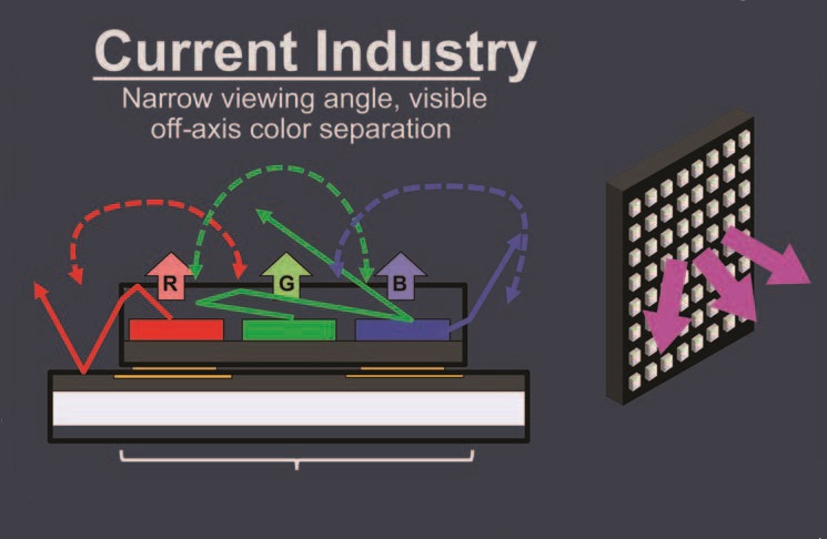
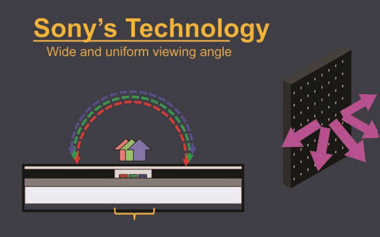
In positioning the camera in relation to the LED display, consideration should be given to off-axis color shifts which might be inherent in the LED wall. A display that doesn’t exhibit brightness or color shift when viewed from different angles will provide more flexibility in camera blocking, and dolly and crane moves and allow for more of the stage area to be utilized.
Staging should also consider camera positions that avoid Moiré artifacts. This may include positioning on-set objects far enough from the LED wall so that the LED pixels are sufficiently de-focused to avoid the Moiré interference pattern. If this isn’t possible, you should choose an LED display with finer pixel pitch to avoid Moiré problems when the background is in-focus.

